
Power Factor Correction & Harmonic Mitigation
MPP Gas Filled Capacitor


- Dry construction: gas-filled, no liquids
- Special low current-density-design & Low heat losses, optimized cooling
- High over-current rating (Is = 300 x IN, Imax = 1.5…1.8 x IN)
- Temperature rating -40/60ºC for all items
- Strong voltage reserve & 10% Permanent Voltage
- 2 Years Warranty
APFC CONTROLLER


- 4-Quadrant-Operation & Optimized switching
- Automatically Identification of the power of connected capacitors
- Automatic and manual operation & Port for connection of a tariff switch
- Separate setting of target and alarm cos phi for two different tariffs
- Port for external alarm & Adjustment of the switching periods in dependence of the load
- Alarm during insufficient measuring current & Zero voltage tripping
- Disconnection of the capacitor bank in the event of excessive harmonic Voltage distortion.
- Variable time for alarm in the event of failed Power Factor correction
- Specification of a Permanent capacitor value in addition to the measured required power. e.g. for compensation of a transformer
- Optional RS485 port for PC or remote control unit.
APFC - Automatic Power Factor Control Panel


APFC or Automatic Power Factor Control Panels are mainly used for the improvement of Power Factor. Power Factor can be explained as ratio of active power to apparent power and it is a key factor in measuring electrical consumption. A dip in Power Factor can attract operational losses and a penalty from electricity board and if the Power factor is maintained to Unity then the consumer can CLAP his shoulders for maintaining it and reduction of demand. APFC Panels automatically manage quickly changing loads along with the retention of high Power Factor.
- From 4 stages to 12 stages, & Rated KVAR: 10 KVAR to 1000 KVAR Standard.
- With Detuned Harmonic filter reactors for Eliminating 3rd, 5th up to 13th order harmonics
- Used in Pharma, process industries, engineering industries, Textiles, Sugar and Steel. (for constant loads)
APFC stands for ‘automatic power factor correction’. An APFC panel consists of multiple capacitors of different ratings whose switching can be controlled as per requirement. An APFC is effective as a single-point installation which can be used to control the power factor for a large number of loads, instead of installing capacitors at the individual locations of each load. Depending on the loads in operation, various levels of kVAR compensation are required to maintain proper power factor. The APFC panel contains a multi-step relay which is connected to multiple capacitors and a microprocessor controller which is programmed to control the switching operation of the relay. The voltage and current are measured on the feeder which is providing supply to the entire group of loads to determine the uncompensated power factor.
Main Features:
- Maintains high Power Factor constantly
- High efficiency
- n-built independent fuses
- Protection from excess power in the system.
- Prevents leading Power Factor in low load conditions
- Clearly marked buttons and indicators
- Minimizes harmonic current
- Easy to use
- Corrosion-resistant
- Long lasting
- Electrical insulation
- Protects electrical equipments
These APFC Panels are put to use in the following:
- Windmills
- Monitoring current harmonics
- Process controllers
- Micro processors
- LT & HT factories
- Electrical installations
- Line voltage analysis
Direct Benefits:
- Reduction in MD kVA
- Reduction in kWHr Consumption
- Reduction in kVAHr Charges
- Avoidance of PF Penalty
- Availing PF Incentive
Indirect Benefits:
- Reduction/Avoidance of End Termination Darkening or Burn Outs
- Reduction/Avoidance of Motor winding Failures
- Improved System Performance due to Healthy Voltage
- Low Electric Break Downs/ Reduced Plant Down Time
Thyristor controlled power regulators for switching application of Capacitors for instantaneous load variations


- Immediate COMPENSATION Of inductive reactive power is Very often the only way to cope with disturbances imposed on the mains by huge, Rapidly changing inductive loads.
- Conventional capacitor switching Devices with Reaction periods of 20…90 seconds cannot comply With Such intensive Requirements.
- The VTM Thyristor Switch Module makes reaction times Of 20 milliseconds possible.
- The switching is done, practically without Reactive effects, at zero voltage level (no voltage between input and Output).
- VTM has a very compact design, convenient Connection, Integral overheating protection, and LED indication for the switching signal and excessive temperature. For powers above 75kvar, a controllable fan is included.
- Features:
- Easy to install Rating 15amps – 162amps ( 15/25/50/75/100 KVAR)
- Voltage 400 – 460v ac & Cooling by Forced air cooling.
- Zero differential voltage of Thyristor with precise automatic zero detection logic. (Zero voltage switching ‘ON’ & Zero Current Switching ‘OFF’)
- Smooth, Fast and Transient Free switching of capacitors.
- Very fine correction of reactive power, which is absolutely advanced & unique.
- Unlimited Soft switching noise less operation.
- Reaction time of 5 milliseconds.
- Protection Features:
- Phase loss indication
- Heat sink over temp trip and Indication
- Circuit Fail Indication
STATIC VAR generator / STATCOM

Technical specification


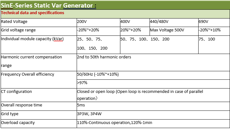

Static var generator/SVG/STATCOM is the new standard in reactive energy compensation. This power electronic current source is the accurate and highly reliable solution for today’s networks characterized by significant increase in harmonics, voltage variations caused by intermittent renewable sources connected to the network and voltage level due to the smart grid development. The DSP controlled IGBT topology enables a perfect compensation on each phase for both inductive and capacitive loads. It also correct phase unbalance where necessary. Immune to harmonics, resonance and voltage level, it offers a maintenance free solution reusable in any network configuration.
SVG Operating Principle:
SVG checks the current through the external CT and performs computing through the external DSP to analysis the reactive content of the load current. After that , it controls the PWM signal generator based on the settings to send control signals to the internal IGBT. In the way, it generates reactive compensation current to implement dynamic reactive power compensation.
- Multifunctional:Reactive power and imbalance compensation
- Excellent reactive compensation:High speed, Precise (-0.99≤Cosφ≤0.99), Step-less, Bi-directional (capacitive and inductance) compensation
- Excellent imbalance correction:Both negative and zero sequence, mitigates neutral current
- Wide input voltage & frequency range Adapts to tough electrical environment
- Low thermal loss (≤3% of rated SVG capacity), efficiency ≥ 97%
- High stability:Infinite impedance to grid, avoids harmonic resonance problem
- Flexible application:Modular design, embedded in standard or customized cabinet
- Easy installation and maintenance:Easy installation for SVG module replacement and expansion
- Wide capacity range:50kvar~600kvar for a single cabinet, up to 10 cabinets in parallel
- Environmental adaptability:-10~50°C temperature, compatible with diesel generators
- Complete protection:Grid over/under voltage, SVG over current, over temperature, and others. All faults recorded in event log, convenient for failure analysis
SVG Application Field:
- Electric Arc Furnaces – voltage stabilization reduces tap-to-tap time and electrode consumption.
- Rolling Mills – elimination of voltage and harmonic distortions reduces reactive power demand and increases electrical system capacity.
- Mining and heavy industry – dynamic reactive power compensation stabilize the power system, especially on large motor start up, ensuring reliability of the power system.
- Wind and solar farms – meeting strict grid connection criteria by providing dynamic voltage control and voltage stability at the common coupling point (PCC). Renewables markets – including solar farms, wind farms, solar panel installations.
Active Harmonic Filter

The Active Harmonic Filters offered by us guarantee highly effective compensation even in the presence of highly asymmetrical loads.
Latest technology to eliminate harmonic injected into the mains supply by non9linear loads, as well supplies inductive power demanded by the load, so as to correct input power factor to near unity.
- Free Standing / Wall mounted.
- System Voltage: 400 V to 480 V, 3 Phase 4 wire.
- Rating: 30 amp to 600 amp
- Filtration from 2nd to 50th order harmonics.
- Can be interfaced with Ethernet / web server.
- Powerful DSP
- Touch Screen display with multiple monitoring system.
Ratings Available:
- Current rating: 30-600A
- three phase available
- Modular design – the system as you grows
- Powerful DSP-Better control over the entire load cycle
- Wide voltage window-with inbuilt Auto Transformer
- Priority Setting-Power factor or Harmonics corrections.
- Global or selective harmonics compensation
- Unbalance correction
- Flicker correction
- Remote monitoring, maintenance and upgrades
- Need Help with Easier Industrial Solutions? We Are Experts!